
Lately, I have been doing some experiments with programmable controllers. One of my projects has been with controllable switches and Arduino. In fact, my programming club had a problem, where this month’s speaker backed-out. With six days to go, the club president asked if anyone would like to present. I stepped up.
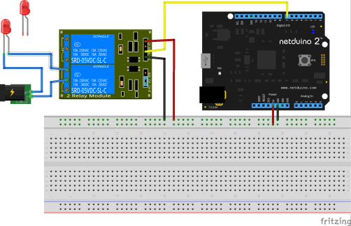
I thought it would be good to show a nice diagram of my project. I noticed that most people use a program called Fritzing, to do the diagrams. This program is great, but it does not have all of the parts that are commonly used with Arduino.
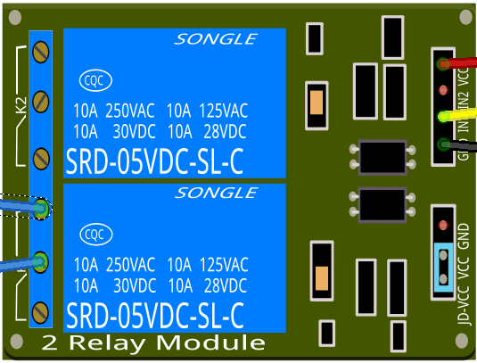
The program allows you to design your own parts. However, the part designer is very fussy. After a bunch of searching and trying, I managed to design a part that looks very similar to my SunFounder 2 Channel 5V Relay Shield Module.
I thought it might help a few people if I shared it. I’m pretty sure that it is not perfect (not-even close), but it is better than nothing. If you are using another 2 channel relay shield module, this is pretty close.
You can download it from my OneDrive: Fritzing part for SunFounder 2 Channel 5V Relay Shield Module
If you would like to make improvements to it, I would be glad to update my Fritzing part. If anyone is interested, I could probably make this into a 4-channel or 8-channel, without too much effort. Just ask (below).

Can you make this into an 8 relay? It would really help me out!
A one channel would be helpful too, I am using something similar for my project:
http://www.ebay.com/itm/5V-10A-one-1-Channel-Relay-Module-With-optocoupler-For-PIC-AVR-DSP-ARM-Arduino-/310636242802
I would love a 4-channel. Like this one:
http://www.dx.com/p/arduino-compatible-4-channel-relay-shield-module-144762#.VdGtdbT6Q1E
Okay. I had trouble getting it to scale properly, but I think I’ve got it now. I made a different blog post for it. https://timgolisch.wordpress.com/2015/09/12/fritzing-4-channel-relay-part/ Enjoy!
Thanks for doing this !
I’m setting up ArdLAb and I needed this. You saved me some very frustrating hours.
And another thanks for doing this. This will help me illustrate what I have been trying to do.
Thanks!
Thanks for models! 8 relay would be very helpful 🙂
Thanks you so much. Can’t understand why such a popular board is not on the basic parts…
do you have the fritzing part for the relay? can’t seem to find it anywhere.
There is one relay part that comes with Fritzing, but it looks weird. It is black and appears to be sort-of 3d. All of my relays at home are orange or blue, so I don’t really like the relay that comes with Fritzing. Gosh, maybe I should make a single orange or blue relay part. That might be cool.
Hello,
I’m just starting with Fritzing.
I need a 2 relays board. I have well downloaded the files from Tim.
I managed to create a new component and replace the breadboard and PCB pictures.
But for the Shematic picture I don’t fine any in the zip.
Can someone help.
Thanks in advance.
Patrick.
hey thanks man. I used it, good job!
Thank you for you job !
Is fine!
If anyone could send some good links or helpful information on what tools and the easiest approach to creating images to import into the Fritzing tool. It is quite a handy tool.
can you please create 3 channel relay
hi, thx for this module
doesn’t work with “autoroutage” for drawing board in Frtzing
Hello,
Could you please make another one, 6 channel 12v relay?
Thank you in advance,
Gary.
Many Thanks Tim!
I intend to use it on my project.
Thanks for this component !
thank you
Hi. Those links are not working anymore. Could u check, please?
Nice work, btw!
Can you create 6 channel relay module please
Thank you.
Pingback: How to make an automatic sprinkler controlled by Telegram with the ESP8266 NodeMCU – Techrm
Pingback: Come realizzare un irrigatore automatico comandato da Telegram con il NodeMCU ESP8266 – Techrm
It would be nice to not force the jumper, I need to apply two different voltage and so can’t use your part
The light-blue jumper is element “rect4848”. You could use a program like inkscape to remove that blue rectangle (jumper) from the breadboard.svg (vector graphic) file. If you don’t like inkscape, you could even open that same svg file with notepad and just find/replace the value “66D0ED” with “000000” (effectively erasing the jumper by making it black). The fritzing part file (2-Channel 5v Relay Shield.fzpz) is really just a zip file, containing a few graphics and a manifest. Easy to edit & save your own changes.
Pingback: Come creare un sistema di irrigazione automatica con ESP8266 controllato da Arduino Cloud - Techrm
Pingback: How to make an automatic sprinkler with ESP8266 controlled by Arduino Cloud - Techrm
Pingback: ESP8266 Web Data Logger: creare una pagina web per visualizzare i dati di temperatura e umidità - Techrm
Pingback: ESP8266 Web Data Logger: create a web page to view temperature and humidity data - Techrm
Pingback: RFID access control with ESP8266: a simple solution - Techrm
Pingback: Controllo accessi RFID con ESP8266: una semplice soluzione - Techrm